
 Business License

What Is a Carbide Pilot Punch? Definition for Stamping and Piercing Dies
1. What the Carbide Pilot Punch Definition Covers in Stamping and Piercing Dies
A stamper running 0.8 mm cold-rolled steel in a progressive die saw hole diameter drift two weeks after a tool service. The punch tip had moved 0.02 mm, inside the drawing tolerance and outside the part tolerance. By the time the drift was traced, roughly 4,000 brackets had gone to deburring with a burr nobody had specified.
That failure sits behind most of the questions buyers bring to us about the carbide pilot punch definition. The term describes a small carbide pin that enters the sheet first and carries the cutting edge through it, not a locating pin that sits outside the cut. Most of the confusion in a request for quotation comes from that single distinction.
This article walks through what the part is, how it is built, where it sits in a die, and which numbers a drawing has to state before a supplier can quote it. It stays on the component itself rather than on press selection or die design as a whole.
2. Where a Carbide Pilot Punch Sits Inside a Piercing Die
In a piercing station the punch enters through a stripper plate, crosses the sheet, and lands in a die button below. The carbide pilot punch is the component that does the crossing, and its tip geometry decides whether the cut starts on a clean edge or on a sheared one.
Clearance is set by the die designer and normally lands between 5 and 8 percent of sheet thickness per side. On 0.8 mm steel that is roughly 0.04 mm to 0.06 mm, a band narrow enough that punch diameter drift shows up as a rolled edge before it shows up as a measurement.
The stripper plate holds the sheet flat while the punch withdraws, and a weak stripper spring turns a sound punch into a slug pull. Strip force typically runs at 5 to 10 percent of the piercing force, so a die cutting 12 tonnes needs 0.6 to 1.2 tonnes of stripping.
On a die of that size the pin path is set by the stripper and the punch plate together, and a 0.03 mm offset at the plate becomes a visible step at the tip over a 40 mm shank. Winray New Materials measures tip runout with the shank held in a plate-level fixture for that reason, because a pin checked in free air will read true and still cut off centre.
3. Head, Shank and Tip: How a Tungsten Carbide Punch Pin Is Built
A tungsten carbide punch pin is ground from a solid blank in three functional zones, and each zone answers a different question on the drawing. The table below sets out what each zone does and what it looks like when it gives way.
| Zone | Function | Drawing item | Typical failure |
|---|---|---|---|
| Head | Seats against the punch holder and transfers load | Head diameter, head thickness, seat radius | Head shear, seat fretting |
| Shank | Guides the pin in the plate and carries length | Shank diameter, overall length, concentricity | Shank wear, bending |
| Tip | Performs the cut and sets hole size | Tip diameter, corner form, land length | Chipping, diameter drift |
The tip carries the tolerance that matters. Our standard reference is Ø9.525 mm, with diameter held to h6 or h7 when the die designer specifies it, and the cutting land finished to Ra 0.2 to 0.4 μm or better. Those three figures together describe a pin that will hold a hole.
Hardness sits at HRA 89 to 92 in tungsten carbide, which converts to roughly 1,400 to 1,600 HV. That band keeps compressive strength high enough for thin sheet and leaves enough toughness for the interrupted cuts that appear on 3 mm plate.
4. Punch Pin Stamping Die Types: Single Hit, Progressive and Transfer
The same punch pin stamping die family covers three layouts, and each one puts a different load cycle on the pin. Strokes per minute and pin count per die tell a buyer more about expected wear than the material grade does.
| Layout | Strokes per minute | Pins per die | Wear pattern |
|---|---|---|---|
| Single hit | 40 to 120 | 1 to 4 | Uniform and slow |
| Progressive | 150 to 400 | 8 to 30 | Station dependent, tip led |
| Transfer | 20 to 60 | 4 to 12 | Impact led, head side |
Progressive work is the harshest setting for a small pin. At 300 strokes per minute the pin makes 18,000 contacts an hour, so a 0.01 mm wear step per 10,000 strokes becomes a visible burr within two shifts.
Transfer dies hit harder and far less often, which moves the failure mode from wear to impact. Head shear and seat fretting show up before tip wear does, so the drawing has to specify the head and the seat radius rather than concentrating on the tip alone.
Layout also decides how many spares a shop holds on the shelf. A progressive die running 30 pins at 300 strokes per minute will use a set of tips inside a few months, while the same pin count in a transfer die can last a year at a third of the contacts.
5. Why Carbide Replaces Tool Steel in a Punch Pin Stamping Die
Tool steel punches work, and plenty of dies still run them. The case for carbide is dimensional rather than promotional: tungsten carbide holds diameter through the heat and load cycles that move hardened steel by a measurable amount.
A hardened HSS punch at 62 to 64 HRC loses roughly 0.01 to 0.02 mm of diameter per 100,000 strokes on 1 mm mild steel. A tungsten carbide punch pin in the same station typically holds within 0.005 mm over the same interval, which is why the change is usually made when a part tolerance tightens below 0.03 mm.
Carbide is brittle, and the trade is real. A carbide pin will chip on a misaligned strike where HSS would deform and recover, so the die has to be aligned and the stripper has to be stiff before the material change pays for itself.
Winray New Materials Co Ltd grinds these pins from WC-Co blanks with a grade chosen for the sheet being cut. The grade is settled at quotation rather than after the first breakage, because regrinding a grade that is too hard for the job just moves the failure to the next station.
6. Hardness and Compressive Strength in a Tungsten Carbide Punch Pin
Hardness gets quoted, and compressive strength decides the job. A tungsten carbide punch pin at HRA 89 to 92 carries a compressive strength in the region of 4,000 to 4,600 MPa, several times what hardened tool steel manages.
That margin is what allows a 3 mm pin to pierce 1.5 mm stainless without buckling. Buckling load scales with the fourth power of diameter, so halving the tip diameter cuts the critical load by a factor of sixteen.
Toughness is the counterweight. Cobalt content raises toughness and lowers hardness, and the balance point shifts with sheet thickness, so thin sheet favours the harder end of the grade range while heavier plate favours the tougher end.
We keep three acceptance figures on the inspection record, namely hardness, transverse rupture strength and density, because a hardness value on its own cannot separate a well-sintered blank from a porous one that will fail early.
Winray holds a reference pin from the first article of every custom run, so a reorder a year later returns the same tip diameter, land length and corner form instead of a fresh reading of the drawing. For a die that has already been tuned around a specific pin, that continuity saves a full setup cycle.
7. Tolerances That Make a Carbide Pilot Punch Definition Useful on the Floor
A definition that stops at "carbide pin" does not help a buyer place an order. What makes the carbide pilot punch definition actionable is the shorter list of tolerances the drawing has to carry, and the table below is the one we work to.
| Feature | Specified as | Why it matters |
|---|---|---|
| Tip diameter | h6 or h7 on request | Sets hole size and cutting clearance |
| Concentricity, tip to shank | 0.005 mm | Prevents side load and edge chipping |
| Squareness of tip face | 0.01 mm | Keeps the cut edge even around the hole |
| Land length | 0.5 mm to 1.5 mm | Balances edge support against friction |
| Surface finish | Ra 0.2 to 0.4 μm | Controls friction and burr height |
Length tolerance is the item buyers leave off the drawing. A pin 0.1 mm short seats late and a pin 0.1 mm long preloads the holder, and both faults appear as a burr on a single side of the hole.
Corner form belongs on the same sheet. Flat, chamfered and radiused tips cut the same diameter and behave differently on withdrawal, and a radiused tip on thin brass leaves a cleaner edge than a sharp corner does.
8. Reading a Punch Pin Stamping Die Failure Against the Definition
Failure reading works backwards from the part. A burr on one side of the hole points at alignment, a burr around the full circumference points at clearance or tip wear, and a cracked hole edge points at a chipped land.
A connector stamper we worked with was replacing pins every 30,000 strokes on 0.4 mm phosphor bronze. The complaint was short life, and the measurement showed a 0.03 mm offset between punch and die button that the pin had been absorbing as side load.
Realigning the station and moving from a default h7 to a specified h6 with 0.005 mm concentricity took the same pin past 250,000 strokes. Nobody changed the carbide grade, the press or the running speed.
That is the working value of a tight punch pin stamping die definition, because it tells the tool room which of four figures to measure first. Without it the repair defaults to buying a harder grade, which answers a hardness question and leaves the offset in place.
Winray keeps a short failure record with each custom order for exactly that reason. When a customer returns to a second design, the previous offsets and clearances are on file instead of being rediscovered on the press.
9. Frequently Asked Questions About the Carbide Pilot Punch Definition
9.1 Is the Carbide Pilot Punch Definition the Same as a Pilot Pin?
No, and the two are confused in a large share of quotation requests. A pilot pin locates the strip or the workpiece before the cut and carries no cutting edge, which is why its nose is usually rounded or chamfered. A carbide pilot punch definition covers the component that enters the sheet and shears it, so its tip is ground square with a defined land and clearance. Ordering a pilot pin for a station that needs a punch returns a part that will not cut, and the tip form on the drawing is where the difference shows first.
9.2 What Sheet Thickness Range Does a Punch Pin Stamping Die Handle?
A punch pin stamping die handles thin sheet from about 0.2 mm up to heavy plate near 6 mm, and the pin changes across that range more than the die frame does. Below 0.5 mm the limiting factor is buckling, so the tip needs a short land and a stout shank behind it. Above 3 mm the load moves into the head and the seat, which means head thickness and seat radius take over the specification. Carbide is usually chosen in the 0.3 mm to 2 mm band, where the tolerance gain and the tool life both justify the material cost.
9.3 How Tight Should a Tungsten Carbide Punch Pin Fit a Die Plate?
A tungsten carbide punch pin normally runs with 0.005 mm to 0.015 mm of diametral clearance in the punch plate, enough to slide freely without binding. Too tight and the plate grips the shank, which pulls the tip off line on the return stroke. Too loose and the pin tilts under side load, which is the usual cause of a chipped land on an interrupted cut. We hold concentricity between tip and shank to 0.005 mm so that the plate clearance can stay at the tight end of that band without seizing.
9.4 Can a Punch Pin Stamping Die Run Carbide in a Mechanical Press?
Yes, provided the press is in reasonable condition and the die set is guided. A mechanical press with 0.05 mm of ram play will tilt a small carbide pin on every stroke, and the land chips before the tip shows measurable wear. Ball-bearing die sets and a stiff stripper plate take most of that play out of the pin path. Where ram play cannot be reduced, a tougher carbide grade or a return to HSS is the sensible answer, and we raise it at quotation rather than after the first breakage.
Recently Posted
-
Carbide Punch Pins in Progressive Die Piercing of Sheet Metal
November 18, 20261. Progressive Die Punch Pin Loads at 300 Strokes a Minute A progressive die punch pin does not do one job. It does the job of its Read More
-
How to Order Custom Carbide Punch Pins From a Drawing
November 17, 20261. Why a Punch Pin Drawing Carries More Than a Part Number A part number describes a pin that already exists. Beyond the standard
Read More -
Solid Carbide Punch Pin vs Coated Punch: Which Holds Diameter Longer
November 17, 20261. Why a Solid Carbide Punch Pin and a Coated Punch Are Compared Wrong A solid carbide punch pin is usually compared with a coated Read More
-
Carbide Punch Pin vs HSS Punch: Wear Life per 100,000 Strokes
November 17, 20261. Why Punch Cost per Stroke Is a Better Question Than Pins per Year A terminal stamper a while back asked us to quote a punch pin Read More

Contact Us
Recommended Products
-
 Non-Magnetic Nickel-Bonded Cemented Carbide Molds, Submicron Grain, Mirror Polished CavitiesNegotiableMOQ: 1 Blade
-
Non-Magnetic Carbide Grades for Specialized MoldsNegotiableMOQ: 1 Unit
-
Tungsten Carbide Punches HRA 90.5 Co 10% +/-0.002 mm Tolerance Mirror-Polished for Stamping DiesNegotiableMOQ: 1 Unit
-
Custom Carbide Strips and Round Blanks With 0.05mm Flatness for Machine ToolingNegotiableMOQ: 1 Unit
-
Custom Cemented Carbide Blanks ISO Standard Compliant With Ra 0.4 Surface FinishNegotiableMOQ: 1 Unit
-
Precision Ground Carbide Inserts and Blanks – Custom Grades and Tolerances up to ±0.01mmNegotiableMOQ: 1 Unit
-
Ground Carbide Rods Ø8mm x 200mm, h6 Tolerance, Ra 0.4μm, HRA 91.0NegotiableMOQ: 10 Units
-
Polished Tungsten Carbide Hollow Rods for Precision Machining ApplicationsNegotiableMOQ: 1 Piece
-
Tungsten Carbide Saw Tips for TCT Circular Saw Blades and Woodworking CuttingNegotiableMOQ: 100 Pieces
-
Tungsten Carbide Gripper Inserts for Oilfield Slip Assemblies – YG8/YG6/K10 Grades, High Hardness & Wear ResistanceNegotiableMOQ: 5 Kilograms
-
Precision Carbide Sleeves OD 5-50 mm ID 2-30 mm Concentricity Max 0.005 mm Ra 0.2 um CNC GroundNegotiableMOQ: 1 Unit
-
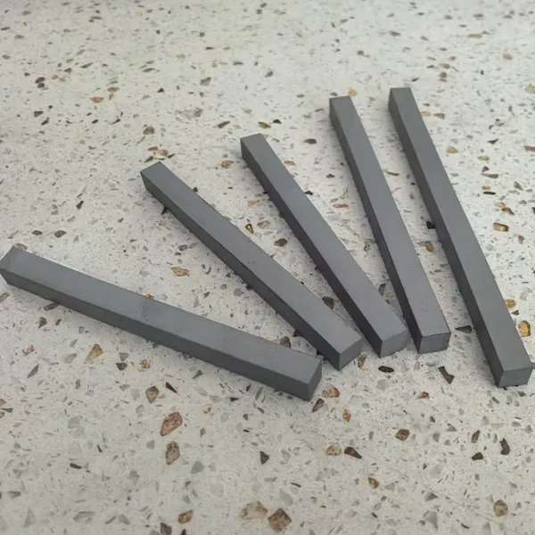
Submicron Tungsten Carbide Strips 2x8x330mm Ground Tolerance ±0.02mm HRA 92.0NegotiableMOQ: 10 Pieces
-
VSI Crusher Carbide Strips and Bars for Machine Tool Plane Blades Wood Cutting ToolsNegotiableMOQ: 10 Units
-
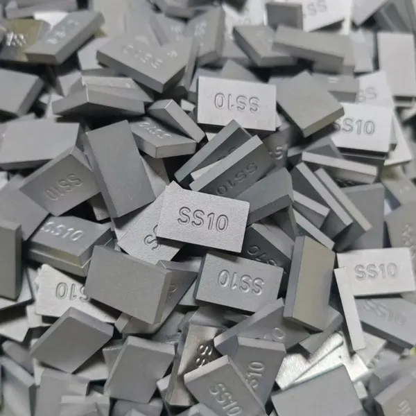
Yg8 Standard Tungsten Carbide Tips Ss10 for Stone Cutting ToolsNegotiableMOQ: 5 Kilograms
-
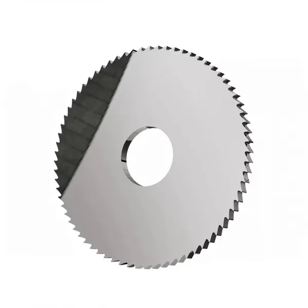
Tungsten Carbide Circular Saw Blade for Slitting Slotting Flat Tooth Saw Blades Cutting Metal Stainless Steel Aluminium Custom OEM Factory Bulk PriceNegotiableMOQ: 1 Blade
-
Tungsten Carbide Woodworking Blades – Replacement Cutting Blades for Wood Carving, Trimming & Planing ToolsNegotiableMOQ: 1 Box
-
Custom Carbide Wear Components From Samples and Prototypes to Volume Production WC-Co SupplierNegotiableMOQ: 10 Blades
-
Custom Tungsten Carbide Wear Parts Non-Standard Shapes Produced to Customer Drawings WC-CoNegotiableMOQ: 10 Blades
-
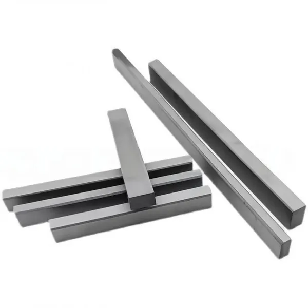
Tungsten Carbide Strips and Plates PYG7 Submicron Grade M10 Ultra High Strength Custom SizesNegotiableMOQ: 10 Blades
-
Tungsten Carbide Strips and Plates PK08 Grade K30 High Strength Impact Resistant Custom SizesNegotiableMOQ: 10 Blades