
 Business License

How to Order Custom Carbide Punch Pins From a Drawing
1. Why a Punch Pin Drawing Carries More Than a Part Number
A part number describes a pin that already exists. Beyond the standard Ø9.525 mm shank with a flat tip, most pins in service are one-off parts that exist as a drawing and a lot record rather than as a catalogue line.
The gap sits in the details a number cannot carry. Head thickness, seat radius, tip form, corner break and tolerance class all live outside the nominal diameter, and each of them changes how the pin behaves once it is in the press.
A connector stamper we supply ran into this with a pin ordered from a catalogue number. The replacement arrived with a head 0.3 mm thinner than the original, sat 0.3 mm lower in the retainer, and moved the tip protrusion by the same amount. The first-off parts ran past the burr limit and the press stopped while somebody measured the head with a micrometer.
What follows covers the order from the drawing side: what the drawing has to contain, what it usually leaves out, how to set the quantity, and what to check on the first article before the lot is accepted.
2. What a Punch Pin Drawing Checklist Must Contain
A punch pin drawing checklist fits on one page, and a good share of the orders that reach us arrive without one. The eight items below are what we ask for before a quotation leaves the office, because every missing one turns into a question after the material is cut.
| Item | Why the shop needs it | Typical value |
|---|---|---|
| Overall length | Sets tip protrusion against the die height | 40 to 120 mm |
| Head diameter and thickness | Locates the pin and takes the stripping load | 1.5 to 2 times shank diameter, 3 to 6 mm thick |
| Shank diameter with tolerance class | Sets the fit in the retainer bore | Ø9.525 mm h6 or h7 |
| Tip form and land width | Decides burr height, slug pull and edge strength | Flat, chamfered or radiused; land 0.2 to 0.5 mm |
| Tip corner break | Removes the stress riser that chips first | 0.1 to 0.2 mm at 45 degrees |
| Surface finish, shank and tip | Controls the fit and the friction at the land | Ra 0.2 to 0.4 μm |
| Grade and hardness | Sets the balance between wear and impact | HRA 89 to 92, cobalt adjusted to the sheet |
| Quantity and marking | Sets the price band and the traceability | Lot number marked on the head |
Two rows deserve a sentence each. The corner break looks cosmetic and is not, because an unbroken edge concentrates load on a corner with no material behind it, and that corner is where a chipped pin starts.
The tolerance class on the shank is the other. Writing a bare Ø9.525 mm leaves the grinder to pick the middle of the general tolerance table, which can land the pin 0.02 mm loose in a bore that was machined to hold it.
3. Dimensions the Punch Pin Drawing Usually Omits
A punch pin drawing checklist rarely reaches the four features below, and those four are where the failures begin. None of them is a dimension of the pin in isolation; each is a relationship between the pin and the die.
| Omitted feature | Where the figure comes from | What it costs when missing |
|---|---|---|
| Tip protrusion above the stripper | Die height and retainer depth | Clearance changes once the pin is in the press |
| Seat radius under the head | Stripping load and head thickness | Head shear starting at a sharp corner |
| Tip to shank concentricity | Grinding setup and inspection method | Crescent hole, side load, uneven wear |
| Underhead fillet | Head flex allowance | Fatigue crack after a few hundred thousand strokes |
Tip protrusion is the one that surprises buyers, because it is not a number on the pin at all. The pin can be ground to length perfectly and still sit wrong if the retainer depth was measured from a different face than the drawing assumed.
Concentricity is the one that shows up as a quality problem rather than a tooling problem. A tip running 0.02 mm off the shank axis cuts a hole on one side and rubs on the other, and the operator reads it as a clearance issue that no shim will fix.
4. Reading the Die Layout Before a Punch Pin Quotation
A drawing without the die layout and the sheet specification is half an order. The layout says which stations the pin serves, whether it pierces or pilots, and how much support the stripper gives it on the return stroke.
Four figures from the layout change the recommendation before price enters the discussion. Sheet thickness and grade set the impact load at the tip, cutting clearance sets how the edge wears, and stroke rate sets how often the pin meets that load. The number of stations decides whether one pin change stops the whole die.
| Layout figure | Range we see | What it changes |
|---|---|---|
| Sheet thickness | 0.3 to 3.0 mm | Grade toughness and tip land width |
| Cutting clearance per side | 5 to 8 percent of thickness | Edge wear pattern and burr height |
| Stroke rate | 60 to 600 per minute | Whether wear or impact decides life |
| Stations served | 1 to 12 | Whether one pin change stops the whole die |
Clearance is the figure most often left off because each department assumes another one recorded it. A die that has been shimmed twice has a clearance nobody can state, and any pin quoted against that die is quoted on an assumption.
When the layout is missing we quote against the sheet thickness the customer names and flag the assumption on the offer. That flag has saved more than one order from becoming a complaint about a pin that was correct for a different press. A custom carbide punch pin order that carries the layout avoids the flag altogether, and Winray New Materials treats the attachment as part of the enquiry rather than as an extra.
5. Punch Pin Grade and Tolerance Selection on the Order Line
The hardness band for a punch pin runs HRA 89 to 92, and cobalt content moves the pin within that band. A grade at the hard end holds diameter longer, while a grade at the tough end absorbs impact the hard one cannot.
We quote a grade against the sheet rather than against the customer's previous supplier. A pin selected for 3 mm plate and then run on 0.5 mm sheet tends to chip at the corner long before it wears at the land.
| Duty | Grade position | Shank tolerance | Tip form |
|---|---|---|---|
| Thin sheet at high stroke rate | Hard end, HRA 91 to 92 | h6 | Flat with 0.1 mm break |
| Mixed sheet, general work | Middle, HRA 90 | h6 or h7 | Chamfered |
| Thick sheet or heavy impact | Tough end, HRA 89 to 90 | h7 | Radiused |
| Stainless and adhesion-prone work | Middle to hard | h6 | Chamfered with lapped land |
Surface finish belongs on the same line as tolerance because the two act together. A shank ground to h6 at Ra 0.4 μm holds a different fit from the same shank at Ra 0.2 μm, and the difference is measurable in the retainer after a few thousand strokes.
This is also the point where a custom carbide punch pin order either gets a grade recommendation or gets a repeat of last time. Repeating a grade without knowing the sheet is how a shop ends up with a pin that worked on one press and failed on its replacement.
6. Punch Pin Order Quantity and What Drives the Price Band
Punch pin order quantity is usually settled inside purchasing and should be settled by the cost structure instead. Setting a grinder up on a new drawing takes two to four hours, and that setup is spread across however many pieces the order carries.
| Order size | Setup share of unit price | Suited to |
|---|---|---|
| 1 to 10 pieces | 60 to 80 percent | First article and trial stations |
| 11 to 50 pieces | 30 to 50 percent | A die set with one spare per station |
| 51 to 200 pieces | 12 to 25 percent | Annual consumption on a running die |
| 201 to 500 pieces | Under 10 percent | Multi-station dies at high stroke counts |
The spares allowance is the second half of the decision. A die with six piercing stations needs at least one spare per station, because a single chipped pin stops the whole die and the line waits on a part that costs less than an hour of production. That rule of thumb, rather than a round number, is what a punch pin order quantity should be built on.
A 12 to 20 percent allowance on the first order covers breakage during setup and the settling-in period on a new station. After the first year the consumption record replaces the estimate, and a shop that tracks pin changes usually finds the real figure sits at the low end.
There is a floor worth knowing. Below five pieces the per-unit price is dominated by setup and inspection rather than by carbide, and a customer comparing that price against a catalogue pin is comparing two different things. Winray quotes the setup as a separate line on trial orders so that comparison stays honest.
7. What Happens Between a Custom Carbide Punch Pin Order and Delivery
A custom carbide punch pin order moves through five stages, and the two that consume the calendar are drawing review and grinding. Everything else is a day.
| Stage | What happens | Days |
|---|---|---|
| Drawing review | Tolerance stack, grade choice, missing dimensions | 1 to 2 |
| Blank cutting and preforming | Carbide rod cut and head formed | 2 to 4 |
| Grinding | Shank, tip and head ground in three setups | 3 to 6 |
| Inspection | Diameter, runout, tip form and finish | 1 |
| Packing | Edge protection and lot marking | 1 |
Review is where an order firms up or goes backwards. A drawing with a tolerance stack that cannot be held, such as an h6 shank with a 0.02 mm concentricity callout at the tip, comes back as a question rather than as a reject six days later.
Grinding is the stage that varies most between suppliers, because a pin ground in three setups carries three chances to lose concentricity. Grinding the shank and the tip in one setup holds the relationship between them; grinding them separately relies on the fixture and on the operator checking runout between operations.
Winray New Materials Co Ltd sends the review notes with the quotation, so the customer sees which dimensions were tightened and which stayed at general tolerance before any material is cut.
8. First Article Inspection on a Punch Pin Order
The first article is where the drawing stops being a document and becomes a part. Six checks cover the features that decide whether the pin will run, and all six fit on one inspection sheet.
| Check | Method | Accept |
|---|---|---|
| Shank diameter | Micrometer at three heights | Inside the stated h6 or h7 band |
| Overall length | Height gauge on a flat plate | Within 0.02 mm of drawing |
| Head thickness | Micrometer across the head | Within 0.02 mm of drawing |
| Tip to shank concentricity | Dial indicator on a vee block | Within 0.01 mm |
| Tip form and corner break | Optical comparator at 20 times | Profile within 0.05 mm |
| Surface finish | Comparator patch or profilometer | Ra 0.4 μm or better |
Hardness is checked on the lot rather than on the part, at HRA 89 to 92, because a hardness test leaves a mark that cannot go on a finished tip. That is why the record cites a lot value and a sample position rather than a reading on the delivered pin.
When an item falls outside, the useful response names the dimension and the amount rather than rejecting the lot. A pin 0.01 mm over on the shank can be reground, while a batch 0.3 mm short on overall length cannot be saved. Winray reports the measured value against each line of that sheet rather than a pass or fail mark.
Approval closes the loop. Once a first article is signed, the drawing and the inspection record become the reference for every repeat order, and a change to either should trigger a new first article rather than a silent substitution. Winray keeps both documents in the lot file so a repeat punch pin order quantity can be quoted against a part that already ran.
9. Frequently Asked Questions About Ordering Custom Punch Pins
9.1 What Should a Punch Pin Drawing Checklist Cover Beyond Dimensions?
Four things beyond the geometry: the tolerance class rather than a bare diameter, the surface finish on both shank and tip, the grade or hardness band with the sheet grade if the application is unusual, and the die layout figures the pin depends on, which are sheet thickness, clearance per side and stroke rate. A punch pin drawing checklist that covers those four along with the dimensions and the quantity answers every question a grinder would otherwise have to ask. We send that sheet with the quotation so the customer can check it against their own die file before ordering.
9.2 How Do I Set Punch Pin Order Quantity for a New Die?
Count the piercing stations and add one spare per station, then add 12 to 20 percent for setup breakage. That gives a punch pin order quantity that covers the start of production without a second order in the first month. The next step is to divide the annual stroke count by the expected pin interval, which tells you whether the first order should already cover the year. Because setup dominates below ten pieces, a first order that stops at two pieces usually costs more per unit than the same order at twenty.
9.3 Can I Order Without a Drawing, Using a Sample Instead?
Yes, with one condition: the sample has to be unworn. A used pin has already lost diameter at the land and often has a rounded corner, so a drawing reverse-engineered from it reproduces the wear rather than the original part. Send an unused pin from the same lot if one exists, or send the die layout with the retainer bore measurement. We measure the sample and issue a drawing for approval before cutting, which turns a verbal order into a punch pin drawing checklist for the repeat run.
9.4 How Long Does a Custom Carbide Punch Pin Order Take?
Seven to fourteen days from an approved drawing on a first order, depending on tip form and how many dimensions need tightening at review. A repeat order against a drawing already in our file runs five to eight days, because review and first-article setup are done. The variable is usually the drawing rather than the grinding. A custom carbide punch pin order that arrives complete, with the tolerance class and the die layout attached, generally ships at the low end of both ranges, and the lead time shortens with it.
Recently Posted
-
Carbide Punch Pins in Progressive Die Piercing of Sheet Metal
November 18, 20261. Progressive Die Punch Pin Loads at 300 Strokes a Minute A progressive die punch pin does not do one job. It does the job of its Read More
-
Solid Carbide Punch Pin vs Coated Punch: Which Holds Diameter Longer
November 17, 20261. Why a Solid Carbide Punch Pin and a Coated Punch Are Compared Wrong A solid carbide punch pin is usually compared with a coated Read More
-
Carbide Punch Pin vs HSS Punch: Wear Life per 100,000 Strokes
November 17, 20261. Why Punch Cost per Stroke Is a Better Question Than Pins per Year A terminal stamper a while back asked us to quote a punch pin Read More
-
Carbide Punch Pin Anatomy: Head, Shank, Tip and Where Each Part Fails
November 16, 20261. Carbide Punch Pin Anatomy: The Three Zones and Why the Split Matters A punch pin ground to the right diameter still fails when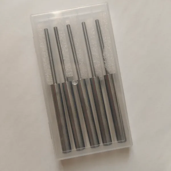 Read More

Contact Us
Recommended Products
-
 Non-Magnetic Nickel-Bonded Cemented Carbide Molds, Submicron Grain, Mirror Polished CavitiesNegotiableMOQ: 1 Blade
-
Non-Magnetic Carbide Grades for Specialized MoldsNegotiableMOQ: 1 Unit
-
Tungsten Carbide Punches HRA 90.5 Co 10% +/-0.002 mm Tolerance Mirror-Polished for Stamping DiesNegotiableMOQ: 1 Unit
-
Custom Carbide Strips and Round Blanks With 0.05mm Flatness for Machine ToolingNegotiableMOQ: 1 Unit
-
Custom Cemented Carbide Blanks ISO Standard Compliant With Ra 0.4 Surface FinishNegotiableMOQ: 1 Unit
-
Precision Ground Carbide Inserts and Blanks – Custom Grades and Tolerances up to ±0.01mmNegotiableMOQ: 1 Unit
-
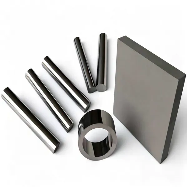
Ground Carbide Rods Ø8mm x 200mm, h6 Tolerance, Ra 0.4μm, HRA 91.0NegotiableMOQ: 10 Units
-
Polished Tungsten Carbide Hollow Rods for Precision Machining ApplicationsNegotiableMOQ: 1 Piece
-
Tungsten Carbide Saw Tips for TCT Circular Saw Blades and Woodworking CuttingNegotiableMOQ: 100 Pieces
-
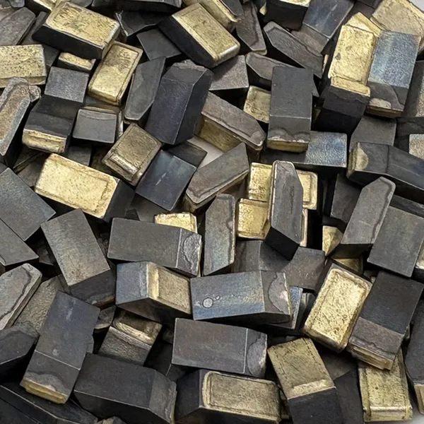
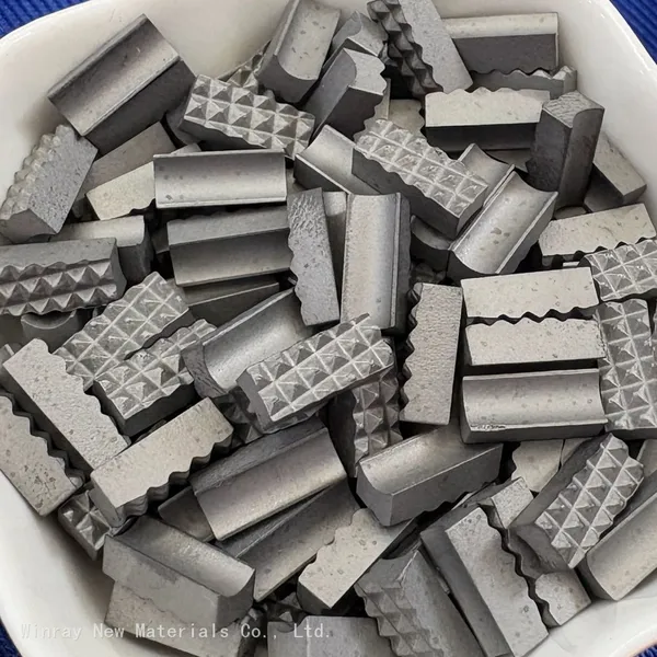
Tungsten Carbide Gripper Inserts for Oilfield Slip Assemblies – YG8/YG6/K10 Grades, High Hardness & Wear ResistanceNegotiableMOQ: 5 Kilograms

-
Precision Carbide Sleeves OD 5-50 mm ID 2-30 mm Concentricity Max 0.005 mm Ra 0.2 um CNC GroundNegotiableMOQ: 1 Unit
-
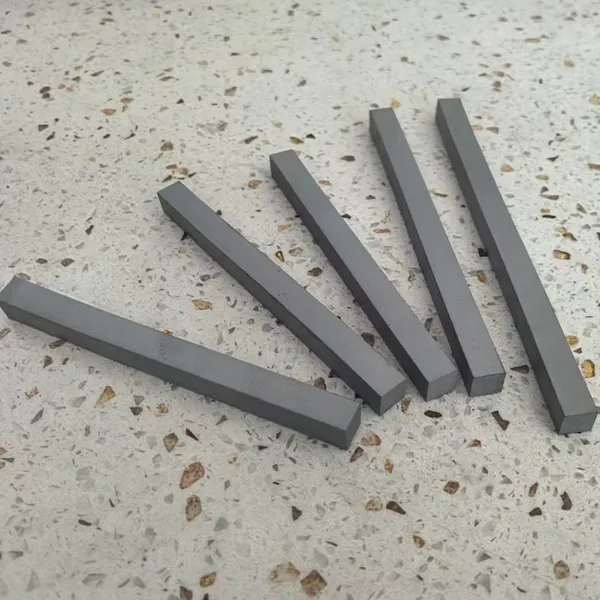
Submicron Tungsten Carbide Strips 2x8x330mm Ground Tolerance ±0.02mm HRA 92.0NegotiableMOQ: 10 Pieces
-
VSI Crusher Carbide Strips and Bars for Machine Tool Plane Blades Wood Cutting ToolsNegotiableMOQ: 10 Units
-
Yg8 Standard Tungsten Carbide Tips Ss10 for Stone Cutting ToolsNegotiableMOQ: 5 Kilograms
-
Tungsten Carbide Circular Saw Blade for Slitting Slotting Flat Tooth Saw Blades Cutting Metal Stainless Steel Aluminium Custom OEM Factory Bulk PriceNegotiableMOQ: 1 Blade
-
Tungsten Carbide Woodworking Blades – Replacement Cutting Blades for Wood Carving, Trimming & Planing ToolsNegotiableMOQ: 1 Box
-
Custom Carbide Wear Components From Samples and Prototypes to Volume Production WC-Co SupplierNegotiableMOQ: 10 Blades
-
Custom Tungsten Carbide Wear Parts Non-Standard Shapes Produced to Customer Drawings WC-CoNegotiableMOQ: 10 Blades
-
Tungsten Carbide Strips and Plates PYG7 Submicron Grade M10 Ultra High Strength Custom SizesNegotiableMOQ: 10 Blades
-
Tungsten Carbide Strips and Plates PK08 Grade K30 High Strength Impact Resistant Custom SizesNegotiableMOQ: 10 Blades