
 Business License

Carbide Punch Pin Anatomy: Head, Shank, Tip and Where Each Part Fails
1. Carbide Punch Pin Anatomy: The Three Zones and Why the Split Matters
A punch pin ground to the right diameter still fails when the wrong zone gave way. Carbide punch pin anatomy splits the component into three functional zones, each carrying a different share of the load and each failing in its own way, so a tool room that knows the split stops guessing what to change.
The head seats against the punch holder and reacts the stripping load. The shank guides the pin through the punch plate and holds the length between holder and sheet. The tip performs the cut and sets the hole size, and it is the zone whose wear reaches the part.
The proportions make a drawing readable at a glance. On the Ø9.525 mm reference shank used here, the head runs 1.5 to 2 times the shank diameter, which is 14.3 mm to 19.1 mm, and is 3 mm to 6 mm thick.
| Zone | Function | Drawing items | Dominant symptom |
|---|---|---|---|
| Head | Reacts the stripping load | Diameter, thickness, seat radius | Fretting at the seat, crack at the fillet |
| Shank | Guides the pin, carries free length | Diameter and class, length | Guide wear, scoring, side load |
| Tip | Performs the cut, sets hole size | Land width, corner break | Chipping, flaking, drift |
Carbide punch pin anatomy reads as three separate specifications rather than one. Each zone has its own drawing items, its own failure signature and its own measurement, and the measurements do not substitute for each other.
2. The Head of a Punch Pin: Seat, Shoulder and Load Path
The head of a punch pin cuts nothing. It reacts the stripping force through a bearing face against the punch holder, which makes it a contact part and a fatigue part rather than a wear part.
Stripping force runs at 5 to 10 percent of the piercing force. On a die cutting 12 tonnes that is 5.9 kN to 11.8 kN, and it arrives as a push against the head shoulder on every stroke instead of a steady static load.
Two radii decide how that push is carried. The seat radius under the head, at 0.3 mm to 0.8 mm, spreads the contact line and stops the shoulder corner from acting as a stress riser, while the underhead fillet at 0.2 mm to 0.5 mm blends shank into head so the transition carries load as a curve.
Head thickness matters for the same reason. A 3 mm head on a heavy stripping load flexes enough to let the pin tilt. Winray New Materials grinds the head and the underhead transition in one setup with the shank, so the fillet stays a true curve and does not crack later.
3. Punch Pin Shank Design: Fit, Length and Alignment
Punch pin shank design has two jobs that pull against each other. The shank must slide freely in the punch plate so the pin returns cleanly, and it must stay straight enough that the tip lands where the holder says it should.
The guide length is the portion held by the punch plate, normally 20 mm to 40 mm, while the free length extends from the plate down to the sheet at 15 mm to 35 mm. Most drawing errors here come from stating overall length without stating where the plate sits.
The fit is a clearance fit quoted as a class. On the Ø9.525 mm reference shank that is h6 or h7 on request, with 0.005 mm to 0.015 mm of diametral clearance in the plate bore on top.
Side load damages a shank, and punch pin shank design is what it comes from rather than the fit. A 0.03 mm offset at the plate becomes a step at the tip over a 40 mm shank, enough to load one corner of the land and chip it.
| Shank parameter | Working value | What it controls |
|---|---|---|
| Shank diameter | Ø9.525 mm reference size | Plate fit and guide stiffness |
| Diameter tolerance | h6 or h7, set by the die designer | Return drag in the plate |
| Plate clearance | 0.005 mm to 0.015 mm diametral | Free withdrawal on the return stroke |
| Guide length | 20 mm to 40 mm | Side load resistance |
| Free length | 15 mm to 35 mm | Tip deflection, alignment sensitivity |
| Tip to shank concentricity | 0.005 mm | Even wear around the hole |
A Ø9.525 mm carbide pin with a 25 mm free length deflects roughly 0.004 mm under a 200 N side load and 0.011 mm under 500 N, while the same pin in tool steel deflects three times as far.
Deflection that small is why the shank rarely breaks in service, and why a bent shank points at a bent holder rather than a weak pin. Punch pin shank design is judged instead on guide wear, which shows up as a pin that binds and then tilts.
4. Punch Pin Tip Geometry: Flat, Chamfered and Radiused
Punch pin tip geometry comes in three forms, and the choice is a decision about entry force rather than hole size. All three cut the same nominal diameter and differ in how much of the edge meets the sheet at entry.
A flat tip runs a full land, 0.2 mm to 0.5 mm wide on the reference size, with a sharp corner. It holds hole size well, but it presents the whole land at once and asks the most of the alignment.
A chamfered tip removes the corner at 45 degrees over 0.1 mm to 0.2 mm, the usual compromise. Entry force drops, the corner stops being a stress riser, and the hole size stays where the drawing puts it.
A radiused tip carries 0.2 mm to 0.5 mm of corner radius and presents the least edge at entry, so punch pin tip geometry decides how gently the edge arrives. It suits tough or abrasive sheet and interrupted work, and leaves the hole slightly oversize, which the clearance calculation must allow for.
| Tip form | Entry behaviour | Suits | What it costs |
|---|---|---|---|
| Flat | Full land engages at once, highest force | Thin sheet where hole size governs | Most sensitive to alignment |
| Chamfered | Corner removed at 45 degrees | General work across most sheet grades | Break must be specified |
| Radiused | Continuous radius, lowest force | Tough or abrasive sheet | Leaves the hole slightly oversize |
Punch pin tip geometry has to carry the corner break on the drawing, because the break is not decorative. An unbroken edge concentrates load on a corner with no material behind it, and that is where a chipped pin starts long before the land nears its wear limit.
Our team grinds all three forms from the same blank and reference size, so changing the form on an existing station is a grinding operation rather than a change of part. That is what makes punch pin tip geometry cheap to revisit once a first run shows where the wear went.
5. Where the Punch Pin Head Fails
The head does not shear off in ordinary service, and the arithmetic says so. The shear capacity of the Ø9.525 mm shank section at a transverse rupture strength near 2,500 MPa is roughly 170 kN, while the stripping load on the same station is 5.9 kN to 11.8 kN, leaving a factor of ten in hand.
What fails first is a contact detail. Fretting at the seat face shows as a bright ring of transferred metal under the head that darkens with time, and it arrives when the pin is loose in the holder. A fatigue crack at the underhead fillet is the second head failure.
A connector stamper we worked with replaced pins every 30,000 strokes and assumed the material was at fault. Measurement showed 0.05 mm of side clearance in the holder, letting the head rock and fret against the holder face, and moving the fit to 0.01 mm with a 0.4 mm fillet took the same pin past 250,000 strokes without a grade change.
Read a head failure as a fit question first and a material question last. Transferred metal means the pin is moving, a crack at a sharp corner means the fillet was wrong, and if both look right Winray looks at the load path above the pin.
6. Where Punch Pin Shank Failures Start
Shank failures are wearing failures. The guide bore in the punch plate takes most of the pin contact, and it wears first because it is the one surface where two hard materials run against each other over the whole travel. Scoring on the shank is the signature.
Buckling is the failure buyers ask about and the one that does not happen. The Euler critical load of a Ø9.525 mm carbide pin on a 100 mm free length sits near 240 kN, and the same pin in tool steel reaches roughly 85 kN, while the piercing load on a comparable station is a fraction of either figure.
The practical shank problem is side load, and it arrives through misalignment. A 0.03 mm offset at the plate becomes a step at the tip over a 40 mm shank, so the shank translates an alignment error into a corner load the tip cannot carry, and the damage is recorded against the tip while the cause sits in the plate.
This is also why the shank is the zone most often left open on a drawing. A pin specified by tip diameter and length alone can arrive with the wrong guide length, and that length sets how much side load the shank absorbs before the tip sees it. Punch pin shank design that names the guide length closes that gap.
7. Where the Punch Pin Tip Gives Up
The tip is the zone whose failure reaches the part, which is why it draws the attention and takes the blame for most of what goes wrong. The three failures look different from each other and each points somewhere specific.
Chipping is an impact failure. It appears as a missing corner on the land, it happens fast, and it usually follows a misalignment, a slug pull, or a step in the sheet. Flaking has a different cause, appearing as a shallow break on the rake side of the land, usually brought on by heat or a grade too hard for the duty.
Abrasive wear at the land is the slow failure, and the diameter drift it produces is what the inspection room measures. On the reference size, carbide holds within 0.005 mm over 100,000 strokes, while a hardened tool steel punch in the same station loses roughly 0.01 mm to 0.02 mm over the same interval.
| Tip symptom | What it is | Where the cause usually is | First check |
|---|---|---|---|
| Missing corner on the land | Chipping | Misalignment or a slug pull | Stripper force, plate alignment |
| Shallow break, rake side | Flaking | Heat, or a grade too hard | Sheet grade, cooling at the station |
| Even land worn across | Abrasive wear | The material being cut | Drift against part tolerance |
| One side bright, one dull | Side load | Plate offset, loose holder | Concentricity, holder fit |
| Raised burr growing each shift | Diameter drift | Wear at the land | Land width against the drawing |
Each row ends in a measurement rather than an opinion. A corner chip sends the tool room to the stripper and the plate, a flaked rake face to the sheet grade and the cooling, a one-sided land to alignment.
Winray keeps the first article of every custom run on file, so a returned pin can be measured against the tip land, the corner form and the diameter that were signed off. That turns a returned pin into a specific finding instead of a second opinion.
8. Reading a Used Punch Pin Back to Its Three Zones
A used pin points to the zone that failed if the right things are measured in the right order. Carbide punch pin anatomy is what the bench sheet below is built around.
| Measurement | Instrument | Reading that confirms the zone |
|---|---|---|
| Shank diameter, three heights | Micrometer | Inside the stated h6 or h7 band |
| Tip to shank runout | Dial indicator on a vee block | Within 0.01 mm |
| Land width | Optical comparator at 20 times | 0.2 mm to 0.5 mm on the reference size |
| Corner form and break | Optical comparator | 0.1 mm to 0.2 mm break where specified |
| Seat face under the head | Visual | Transferred metal or a fretting ring |
| Underhead fillet | Visual | Radius intact at 0.2 mm to 0.5 mm |
| Tip diameter | Micrometer or comparator | Within 0.005 mm of the signed figure |
Order matters. Diameter and runout come before any judgement about wear, because a pin running off axis produces wear that resembles a material problem, and that cannot be diagnosed on a pin that was never straight. The seat face and the fillet come last, and they are worth checking even when the tip looks sound.
Winray New Materials Co Ltd quotes a replacement against these measured figures rather than the original order, so a returned pin showing a wear pattern points at the setting that produced it. That record travels with the new order, which is how a station gets fixed once.
9. Frequently Asked Questions About Carbide Punch Pin Anatomy
9.1 What Is the Difference Between the Head and the Shank of a Carbide Punch Pin?
The head is the bearing end of the pin, and it reacts the stripping force that lifts the sheet off the punch as the tool withdraws, carrying no cutting edge. The shank is the guided length between the holder and the sheet, and its job is to keep the tip on line while the pin moves. The head fails through fretting or a crack at the underhead fillet, while the shank fails through wear in the guide bore of the punch plate. The two zones are separated on the drawing by the shoulder line, and the guide length should be stated so the plate position stays unambiguous.
9.2 How Long Should the Shank Be for a Punch Pin?
Length follows from the stack rather than from preference. Take the head thickness, add the guide length that sits in the punch plate at 20 mm to 40 mm, then add the free length that reaches from the sheet at 15 mm to 35 mm. Total lengths on the Ø9.525 mm reference size run 40 mm to 120 mm, and the free length is worth checking twice because it sets how sensitive the pin is to side load. Punch pin shank design naming all three figures removes the guesswork from where the guide lands.
9.3 Which Tip Geometry Should I Specify for Thin Sheet?
For sheet below 0.5 mm, a radiused or a chamfered tip is the safer choice, because a flat land presents the whole edge at once and thin material does not support the entry load well. The chamfer at 0.1 mm to 0.2 mm is the usual compromise and keeps the hole on the drawing figure, while a flat tip gives the tightest hole size at the price of alignment sensitivity. Where the tolerance is tighter than the sheet supports, punch pin tip geometry should be narrowed at the land rather than sharpened.
9.4 Can a Worn Carbide Punch Pin Be Reground Instead of Replaced?
Sometimes, and the decision follows from the land width. A pin whose land has worn down but still measures 0.1 mm or more can usually be reground back to a workable land by removing a little shank length. Below that figure the pin is normally retired, because a regrind that cuts into the corner to restore the land changes the tip form and the hole size. We check the remaining land and corner before quoting, and the answer goes on the inspection sheet, so the regrind spec follows the part.
Recently Posted
-
Carbide Punch Pins in Progressive Die Piercing of Sheet Metal
November 18, 20261. Progressive Die Punch Pin Loads at 300 Strokes a Minute A progressive die punch pin does not do one job. It does the job of its Read More
-
How to Order Custom Carbide Punch Pins From a Drawing
November 17, 20261. Why a Punch Pin Drawing Carries More Than a Part Number A part number describes a pin that already exists. Beyond the standard
Read More -
Solid Carbide Punch Pin vs Coated Punch: Which Holds Diameter Longer
November 17, 20261. Why a Solid Carbide Punch Pin and a Coated Punch Are Compared Wrong A solid carbide punch pin is usually compared with a coated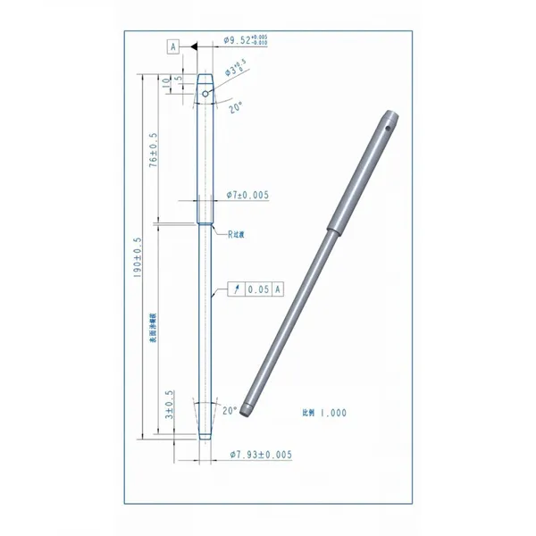 Read More
-
Carbide Punch Pin vs HSS Punch: Wear Life per 100,000 Strokes
November 17, 20261. Why Punch Cost per Stroke Is a Better Question Than Pins per Year A terminal stamper a while back asked us to quote a punch pin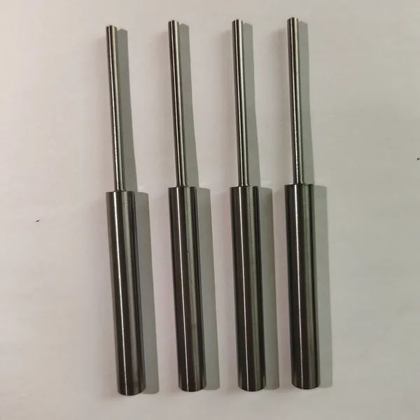 Read More

Contact Us
Recommended Products
-
 Non-Magnetic Nickel-Bonded Cemented Carbide Molds, Submicron Grain, Mirror Polished CavitiesNegotiableMOQ: 1 Blade
-
Non-Magnetic Carbide Grades for Specialized MoldsNegotiableMOQ: 1 Unit
-
Tungsten Carbide Punches HRA 90.5 Co 10% +/-0.002 mm Tolerance Mirror-Polished for Stamping DiesNegotiableMOQ: 1 Unit
-
Custom Carbide Strips and Round Blanks With 0.05mm Flatness for Machine ToolingNegotiableMOQ: 1 Unit
-
Custom Cemented Carbide Blanks ISO Standard Compliant With Ra 0.4 Surface FinishNegotiableMOQ: 1 Unit
-
Precision Ground Carbide Inserts and Blanks – Custom Grades and Tolerances up to ±0.01mmNegotiableMOQ: 1 Unit
-
Ground Carbide Rods Ø8mm x 200mm, h6 Tolerance, Ra 0.4μm, HRA 91.0NegotiableMOQ: 10 Units
-
Polished Tungsten Carbide Hollow Rods for Precision Machining ApplicationsNegotiableMOQ: 1 Piece
-
Tungsten Carbide Saw Tips for TCT Circular Saw Blades and Woodworking CuttingNegotiableMOQ: 100 Pieces
-
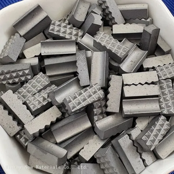
Tungsten Carbide Gripper Inserts for Oilfield Slip Assemblies – YG8/YG6/K10 Grades, High Hardness & Wear ResistanceNegotiableMOQ: 5 Kilograms

-
Precision Carbide Sleeves OD 5-50 mm ID 2-30 mm Concentricity Max 0.005 mm Ra 0.2 um CNC GroundNegotiableMOQ: 1 Unit
-
Submicron Tungsten Carbide Strips 2x8x330mm Ground Tolerance ±0.02mm HRA 92.0NegotiableMOQ: 10 Pieces
-
VSI Crusher Carbide Strips and Bars for Machine Tool Plane Blades Wood Cutting ToolsNegotiableMOQ: 10 Units
-
Yg8 Standard Tungsten Carbide Tips Ss10 for Stone Cutting ToolsNegotiableMOQ: 5 Kilograms
-
Tungsten Carbide Circular Saw Blade for Slitting Slotting Flat Tooth Saw Blades Cutting Metal Stainless Steel Aluminium Custom OEM Factory Bulk PriceNegotiableMOQ: 1 Blade
-
Tungsten Carbide Woodworking Blades – Replacement Cutting Blades for Wood Carving, Trimming & Planing ToolsNegotiableMOQ: 1 Box
-
Custom Carbide Wear Components From Samples and Prototypes to Volume Production WC-Co SupplierNegotiableMOQ: 10 Blades
-
Custom Tungsten Carbide Wear Parts Non-Standard Shapes Produced to Customer Drawings WC-CoNegotiableMOQ: 10 Blades
-
Tungsten Carbide Strips and Plates PYG7 Submicron Grade M10 Ultra High Strength Custom SizesNegotiableMOQ: 10 Blades
-
Tungsten Carbide Strips and Plates PK08 Grade K30 High Strength Impact Resistant Custom SizesNegotiableMOQ: 10 Blades