
 Business License

Carbide Punch Pins in Progressive Die Piercing of Sheet Metal
1. Progressive Die Punch Pin Loads at 300 Strokes a Minute
A progressive die punch pin does not do one job. It does the job of its own station, 300 times a minute, for as long as the coil runs, and it does it while the material around it is being formed and stretched by the stations before it.
The number that governs the interval is contacts rather than strokes. A pin in the third station of an eight station die makes one contact per part, so at 300 strokes per minute it makes 18,000 contacts an hour and 144,000 across a shift. Each of those contacts is a shear event at a hole edge that has never been sheared.
The wear figure behind that count is small in absolute terms and large in effect. A hardened tool steel punch loses roughly 0.01 mm of diameter per 10,000 strokes on 1 mm mild steel, while a carbide progressive die punch pin typically holds within 0.005 mm over the same interval. That gap decides whether a hole still measures or has drifted past what the die button takes.
The progressive layout pushes the arithmetic further, because every station adds a pin to the set that has to be tracked and serviced. A die that pierces, forms and cuts off runs three wear mechanisms against one stripper, and the interval for one station says nothing about the next.
2. What a Sheet Metal Piercing Punch Sets and What Later Stations Change
The sheet metal piercing punch sets the starting hole, and in a progressive die the starting hole is not the hole the customer receives. Stations downstream stretch that hole as the material forms around it, and the growth lands on the part as a hole larger than the one the punch made.
The growth is routine and it is measurable. A pierced hole in low carbon sheet commonly opens by 5 to 15 percent as the surrounding material is drawn, and a flange forming operation adds more because the material is bent across the hole. A 6.0 mm hole in 0.8 mm mild steel can finish at 6.3 mm after a stretch and past 6.9 mm after a flange.
| Where the hole is measured | Typical 6.0 mm hole in 0.8 mm steel | What the number reflects |
|---|---|---|
| As pierced, before forming | 6.00 mm plus die clearance | What the punch set |
| After a draw or stretch | 6.3 to 6.6 mm | Material drawn across it |
| After a flange forming operation | 6.6 to 6.9 mm | Bend added to the stretch |
The consequence for a buyer is that the punch diameter on the order cannot be read as the part tolerance. A pin held to h6 on a 9.525 mm reference is tight enough for the hole it produces and has no bearing on the hole the customer measures. Where the part carries a tolerance, the drawing states the hole after forming and the die designer works back from there.
Winray New Materials asks for the station position and the material flow on a progressive die punch pin order for that reason. A pin ground for station three of one die and fitted into station three of another will be the right diameter and the wrong tool, because the material reaching it is at a different hardness and thickness.
3. Punch Pin Stripper Clearance and the Gap That Decides the Transfer
Die clearance and punch pin stripper clearance are set from different logic, and a buyer who treats them as one number gets both wrong. Die clearance is a cutting dimension at 5 to 8 percent of sheet thickness per side. Punch pin stripper clearance is a relief dimension, and it exists so the sheet releases cleanly from the punch as it withdraws rather than tearing across the hole edge.
The working relationship is simple. Stripper relief should sit at roughly 1.5 to 2.5 times the die clearance, with an absolute floor near 0.05 mm. On 0.8 mm steel the die clearance is about 0.04 mm per side, which puts the stripper relief at 0.06 to 0.10 mm.
| Sheet thickness | Die clearance per side | Stripper relief band | Note |
|---|---|---|---|
| 0.5 mm | 0.03 mm | 0.05 to 0.08 mm | Floor governs |
| 0.8 mm | 0.04 mm | 0.06 to 0.10 mm | Most common case |
| 1.2 mm | 0.06 mm | 0.09 to 0.15 mm | Watch spring |
| 2.0 mm | 0.10 mm | 0.15 to 0.25 mm | Spring load rises |
| 3.0 mm and above | 0.15 mm | 0.23 to 0.38 mm | Spring is the limit |
Two failure directions follow from that band, and they look nothing alike. A relief figure that is too tight shears the sheet edge as the punch withdraws, and the symptom is a raised burr on the part rather than a broken tool. A relief figure that is too generous lets the sheet lift off the stripper as the slug is pushed, and the slug follows the pin out.
Neither symptom gets traced back to the stripper by the shop, because the punch pin stripper clearance is the figure that is assumed to be right. The diagnostic is the part, not the tool: a burr around the hole edge points at the relief figure, and a slug in the press points at the spring load.
4. Work Hardening Changes What a Punch Pin Meets
The material arriving at a piercing station in a progressive die is not the material that came off the uncoiler. Each earlier station stretches it, and stretching low carbon steel raises its hardness. Around 15 to 20 percent cold work moves mild steel from roughly 120 HV to near 180 HV, and a tool cutting into hardened material meets a different load than one that cut the incoming edge.
This is why the first and last stations of a progressive die rarely wear alike. A sheet metal piercing punch at a station placed early cuts soft material and wears on the tip diameter. The same function placed after a draw station cuts a raised hardness level, and the failure shifts from wear to chipping because a harder edge fractures rather than polishes.
There is a second consequence that shows up as a service complaint rather than a tool failure. A pin that has been cutting at a high hardness level and then gets moved to a soft station wears faster than the drawing predicts, because the wear rate is set by the hardest material the pin ever saw.
Winray grinds a progressive die punch pin to the tip condition the customer reports rather than to a house standard, and asks which station it sits in and what runs before it. A reground tip restored to fresh geometry in a hardened station will not last the promised interval.
5. Sheet Metal Piercing Punch Wear Across a Progressive Run
Wear in a progressive die is not one number for the set. Each station sees a different material condition, load and number of contacts, and a tool room tracking one replacement date across the whole die replaces good pins and misses bad ones at the same time.
The table below sets out the pattern on a typical eight station die running 0.8 mm low carbon steel at 300 strokes per minute. The wear figures are diameter loss at the tip, and they assume the material has been lubricated.
| Station | Operation | Material on arrival | Tip wear per 100,000 strokes |
|---|---|---|---|
| 1 to 2 | Blank and pierce | Soft, 120 to 140 HV | 0.002 mm |
| 3 to 4 | Pierce and draw | Stretched, 150 to 170 HV | 0.005 mm |
| 5 to 6 | Form and flange | Hardened, 170 to 190 HV | 0.008 mm |
| 7 to 8 | Cut off and trim | Formed, 180 to 200 HV | 0.010 mm |
Read the right-hand column and the last stations set the service interval for the die, even though the early stations carry the piercing load. A pin in station three holds well beyond the interval a pin in station eight would have worn out, so the die runs until the worst station dictates.
There is a second column of cost in the same table. The 0.008 mm wear rate in stations five and six comes with a harder material condition, and a tip running there wears the seat and the head shoulder as well as the diameter. The failure in that station shows up as a cracked shank or a broken head rather than a hole out of tolerance, and it arrives suddenly.
6. Lubrication, Galling and the Slug a Punch Pin Carries
Sheet metal piercing punch life in a progressive die is set by the lubrication far more often than by the grade, and the mechanism is adhesive wear. Without a film between the stripper and the sheet, the two surfaces weld microscopically at the contact points and the sheet tears as the pin withdraws. The result is the raised burr described earlier, and it appears within the first few hundred strokes.
Oil film thickness has to be a working figure rather than a slogan. A film of 0.005 mm to 0.02 mm is enough to stop adhesive pickup on 0.8 mm to 2.0 mm steel, and a pump delivering a visible bead delivers far more oil than the sheet can hold, so the surplus has to be wiped off before the next station or it tears the material in the corner.
Winray New Materials asks what the line uses and where it is applied when a progressive die punch pin comes back with edge damage rather than diameter wear. A carbide tip that has dulled rather than chipped has usually been running dry or wet, and regrinding it without changing the lubrication puts the same interval back in front of the customer.
7. Failure Modes a Punch Pin Shows Station by Station
Progressive die failures are worth reading as a signature rather than a symptom, because the same visible mark on the part comes from three causes in three places. The table below sets out the pattern that separates them.
| What is seen | Where it points | Check first | Usual cause |
|---|---|---|---|
| Raised burr around the hole edge | Stripper relief | Punch pin stripper clearance | Relief too tight |
| Slug following the pin out | Stripper spring | Spring free length and preload | Spring too weak |
| Hole out of tolerance, drifting | Tip diameter | Punch length and tip wear | Normal wear |
| Corner chip at the tip | Material condition | Which station it came from | Hardened material |
| Mark on the part face | Stripper surface | Plate condition and lube | Galling |
| Cracked shank or broken head | Head and seat | Alignment across the stack | Side load |
Two entries in that table are worth reading twice because they are the ones shops misdiagnose. A slug that follows the pin out of the die looks like a broken tool, and the pin gets replaced before the spring is checked, which puts the same slug back two weeks later. A tip that chips at the corner looks like a grade problem, and the grade gets changed before anyone asks which station it came from.
The common thread in both cases is that the pin is the part that visibly moves and the stripper is the part assumed to be right. Checking the spring and the stripper plate takes ten minutes on the press, and it is the first move that separates a tool problem from a setup one.
8. What to Put on a Progressive Die Punch Pin Order
A punch pin order in a progressive die carries more fields than a single-hit order because the pin is tied to a position rather than a function. The table below is the set Winray New Materials quotes from, and every line changes either the price or the interval of the tool.
| Field on the order | What to state | Why it changes the tool |
|---|---|---|
| Station position | Third of eight | Material on arrival |
| Material and thickness | 0.8 mm low carbon steel | Hardness the tip meets |
| Punch diameter and tolerance | 9.525 mm, h7 | Head geometry and datum |
| Tip geometry | Flat, chamfered or radiused | How the edge enters |
| Length over the shank | 40 mm | Position in the plate stack |
| Stripper and die clearance | 0.04 mm per side, relief band | The punch pin stripper clearance |
| Shank fit | Sliding, 0.01 to 0.03 mm | Guidance in the bore |
| Quantity by station | Set quantities per position | Spare coverage |
The last line is where a buyer saves the most time. Ordering a mixed set by station means every replacement is a matched part, and a die running eight stations needs the counts for eight rather than a single quantity of eight. A mill that orders by position once and keeps the position list with the order replaces a pin without a conversation with the supplier.
Winray New Materials Co Ltd quotes a progressive die punch pin against the station list rather than a total quantity, and it asks for the stripper clearance figure and the material on the same sheet. Those three fields together decide whether the quote is for the tool the die is running or for a similar tool, and they are the fields a supplier cannot guess.
9. Frequently Asked Questions on Carbide Punch Pins in Progressive Dies
9.1 How often should a progressive die punch pin be replaced?
On 0.8 mm low carbon steel at 300 strokes per minute, a pin in the early piercing stations holds well beyond a shift, and a pin in the late forming stations reaches its wear limit in a fraction of one. The practical answer is that the die is serviced when the worst station dictates, not when the average does, so the schedule is set by the last station and the first stations are replaced during the same change. Tracking by station, with the wear rate written against each position, is what makes the schedule a forecast rather than a guess.
9.2 What is the right punch pin stripper clearance for 1.0 mm steel?
For 1.0 mm steel the die clearance runs about 0.05 mm per side, and the punch pin stripper clearance should sit at 1.5 to 2.5 times that, which gives a band of 0.08 to 0.13 mm. Below that band the sheet edge tears as the punch withdraws and the part carries a raised burr. Above it the sheet can lift off the stripper as the slug is pushed, and the slug leaves the die with the pin. The figure that matters more than either is the spring preload, because a weak spring produces the same lifting symptom as a generous relief.
9.3 Can a carbide progressive die punch pin be reground instead of replaced?
Yes, and it is usually the better move for a carbide pin because the tip is the zone that wears. A tip can be reground to its original geometry with 0.1 mm to 0.15 mm of material removed, which on a 9.525 mm pin leaves several regrinds before the shank runs out. Two conditions have to hold. The pin must not have cracked at the head or the seat, because a regrind will not fix a side load, and the material it has been cutting must not have hardened past what the restored edge can hold.
9.4 What makes a sheet metal piercing punch fail in a progressive die but not a single hit?
The progressive layout adds three loads that a single-hit die does not put on the same pin. The material arriving is harder because earlier stations have stretched it, so the tip sees a raised hardness level and the failure shifts from wear to chipping. The pin is one of several in a plate stack, so a small misalignment anywhere in the stack puts a side load on the shank and head. And the stripper is doing work on the sheet while it strips, so the lubrication a single-hit die gets away with is no longer enough.
Recently Posted
-
How to Order Custom Carbide Punch Pins From a Drawing
November 17, 20261. Why a Punch Pin Drawing Carries More Than a Part Number A part number describes a pin that already exists. Beyond the standard Read More
-
Solid Carbide Punch Pin vs Coated Punch: Which Holds Diameter Longer
November 17, 20261. Why a Solid Carbide Punch Pin and a Coated Punch Are Compared Wrong A solid carbide punch pin is usually compared with a coated Read More
-
Carbide Punch Pin vs HSS Punch: Wear Life per 100,000 Strokes
November 17, 20261. Why Punch Cost per Stroke Is a Better Question Than Pins per Year A terminal stamper a while back asked us to quote a punch pin Read More
-
Carbide Punch Pin Anatomy: Head, Shank, Tip and Where Each Part Fails
November 16, 20261. Carbide Punch Pin Anatomy: The Three Zones and Why the Split Matters A punch pin ground to the right diameter still fails when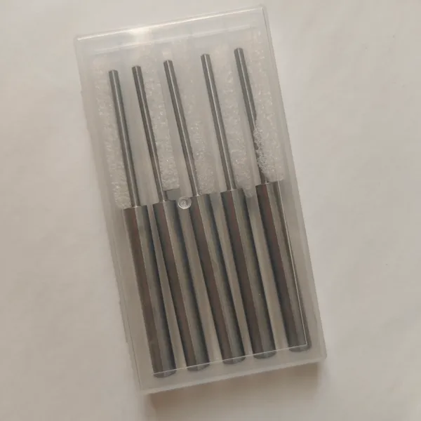 Read More

Contact Us
Recommended Products
-
 Non-Magnetic Nickel-Bonded Cemented Carbide Molds, Submicron Grain, Mirror Polished CavitiesNegotiableMOQ: 1 Blade
-
Non-Magnetic Carbide Grades for Specialized MoldsNegotiableMOQ: 1 Unit
-
Tungsten Carbide Punches HRA 90.5 Co 10% +/-0.002 mm Tolerance Mirror-Polished for Stamping DiesNegotiableMOQ: 1 Unit
-
Custom Carbide Strips and Round Blanks With 0.05mm Flatness for Machine ToolingNegotiableMOQ: 1 Unit
-
Custom Cemented Carbide Blanks ISO Standard Compliant With Ra 0.4 Surface FinishNegotiableMOQ: 1 Unit
-
Precision Ground Carbide Inserts and Blanks – Custom Grades and Tolerances up to ±0.01mmNegotiableMOQ: 1 Unit
-
Ground Carbide Rods Ø8mm x 200mm, h6 Tolerance, Ra 0.4μm, HRA 91.0NegotiableMOQ: 10 Units
-
Polished Tungsten Carbide Hollow Rods for Precision Machining ApplicationsNegotiableMOQ: 1 Piece
-
Tungsten Carbide Saw Tips for TCT Circular Saw Blades and Woodworking CuttingNegotiableMOQ: 100 Pieces
-
Tungsten Carbide Gripper Inserts for Oilfield Slip Assemblies – YG8/YG6/K10 Grades, High Hardness & Wear ResistanceNegotiableMOQ: 5 Kilograms

-
Precision Carbide Sleeves OD 5-50 mm ID 2-30 mm Concentricity Max 0.005 mm Ra 0.2 um CNC GroundNegotiableMOQ: 1 Unit
-
Submicron Tungsten Carbide Strips 2x8x330mm Ground Tolerance ±0.02mm HRA 92.0NegotiableMOQ: 10 Pieces
-
VSI Crusher Carbide Strips and Bars for Machine Tool Plane Blades Wood Cutting ToolsNegotiableMOQ: 10 Units
-
Yg8 Standard Tungsten Carbide Tips Ss10 for Stone Cutting ToolsNegotiableMOQ: 5 Kilograms
-
Tungsten Carbide Circular Saw Blade for Slitting Slotting Flat Tooth Saw Blades Cutting Metal Stainless Steel Aluminium Custom OEM Factory Bulk PriceNegotiableMOQ: 1 Blade
-
Tungsten Carbide Woodworking Blades – Replacement Cutting Blades for Wood Carving, Trimming & Planing ToolsNegotiableMOQ: 1 Box
-
Custom Carbide Wear Components From Samples and Prototypes to Volume Production WC-Co SupplierNegotiableMOQ: 10 Blades
-
Custom Tungsten Carbide Wear Parts Non-Standard Shapes Produced to Customer Drawings WC-CoNegotiableMOQ: 10 Blades
-
Tungsten Carbide Strips and Plates PYG7 Submicron Grade M10 Ultra High Strength Custom SizesNegotiableMOQ: 10 Blades
-
Tungsten Carbide Strips and Plates PK08 Grade K30 High Strength Impact Resistant Custom SizesNegotiableMOQ: 10 Blades