
 Business License

Thin Wall Tube Demand and What It Means for Scraper Design
1. Why the Tube Mill Thin Wall Trend Reaches the Scraper
A tube mill running 25 mm furniture tube a while back moved its wall from 1.4 mm to 1.0 mm to meet a customer's weight target. The weld setting stayed the same, the line speed stayed the same, and the tube mill thin wall trend has continued in the same direction since then, and the internal bead scraper started leaving a mark on the far wall of the tube. The tool had not changed and the tube had, which is the whole story of the tube mill thin wall trend.
Thin wall demand comes from three directions that have nothing to do with each other. Furniture and shelving frames want less weight for the same stiffness. Heat exchanger and condenser tube wants higher heat transfer per unit mass. Structural tube wants the same section modulus from less steel, and the automotive side of that has been the strongest pull.
Each of those markets pushes wall thickness down without pushing tube diameter down by the same amount, so the ratio of wall to diameter falls. That ratio is what a thin wall tube scraper actually responds to, and it is the number worth putting on a tool drawing.
2. What a Thin Wall Tube Scraper Faces That a Standard One Does Not
A standard scraper is designed around a tube that resists the cutting force. A thin wall tube scraper meets a tube that deflects under the same force, and the difference shows up as ovality, as a mark on the opposite wall, and as bead left in place rather than removed.
| Condition | Wall 2.0 mm, 25 mm OD | Wall 1.0 mm, 25 mm OD |
|---|---|---|
| Wall to diameter ratio | 8 percent | 4 percent |
| Section bending stiffness | Reference value | About 12 percent of reference |
| Practical interference depth | 0.25 to 0.40 mm | 0.10 to 0.22 mm |
| Tolerable radial push before marking | 200 to 300 N | 60 to 100 N |
The stiffness figure is the one that reframes the problem. Bending stiffness of a tube wall scales with the cube of thickness, so halving the wall from 2.0 mm to 1.0 mm leaves roughly one eighth of the resistance to a radial load. A cutting force that was harmless at 2.0 mm becomes a visible deflection at 1.0 mm.
The tube does not have to dent to fail. A deflection of 0.05 mm at the scrape point is enough to change the depth of cut, and a depth of cut that varies around the circumference leaves a bead of uneven height and an oval bore. Winray grinds blades for tube from 12 mm to 60 mm outside diameter, which is where that ratio range shifts most.
3. Scraper Design Thin Wall Priorities: Support Before Sharpness
Scraper design thin wall practice inverts the priority order that serves heavy wall tube. On heavy wall the edge geometry leads and the support is secondary. On thin wall the support has to be settled first, because a well-supported mediocre edge cuts better than a finely ground edge on a tube that is moving away from it.
The first support element is a backup roll or a shoe placed within one tube diameter of the cutting point. The further the support sits from the cut, the more tube length is free to deflect, and beyond about three diameters of free span the support stops doing its job.
The second element is the tool holder stiffness. A scraper blade on a slender arbor deflects under load in the same way the tube does, and on thin wall the two deflections add. An arbor that is rigid enough for 2 mm wall can be the limiting component at 1 mm.
The third element is the entry angle. A blade that enters the bead at a shallow angle builds load gradually and lets the support take it, while a blade that drops onto the bead loads the tube before the support has engaged. Winray grinds that angle into the blade rather than leaving it to the setup, because it is the setting most often lost in a tool change.
4. Interference Depth on Thin Wall Tube: Where the Limit Sits
Interference is the depth the blade sits below the bead crest, and it is the setting that thin wall work forces down. A heavy wall line runs 0.30 mm to 0.50 mm of interference and removes the bead in one pass. The same setting on 1.0 mm wall bends the tube section.
| Wall thickness | Interference, OD scarfing | Interference, ID scarfing | Note |
|---|---|---|---|
| 3.0 mm and above | 0.35 to 0.55 mm | 0.30 to 0.50 mm | Single pass, forgiving |
| 2.0 mm | 0.25 to 0.40 mm | 0.22 to 0.35 mm | Standard tooling works |
| 1.5 mm | 0.18 to 0.28 mm | 0.15 to 0.25 mm | Support roll advisable |
| 1.0 mm | 0.10 to 0.22 mm | 0.08 to 0.18 mm | Support roll required |
| 0.8 mm | 0.08 to 0.15 mm | 0.06 to 0.12 mm | Two-pass or skip scarfing |
Reducing interference below about 0.10 mm turns the operation into a polish rather than a cut. The bead crest is smoothed and the bead root stays, and the residue shows up later in a flattening pass or in a customer's bending operation.
The practical answer on very thin wall is often two passes at reduced depth rather than one pass at the limit of what the section tolerates. The second pass costs a tool station and saves the tube.
Winray New Materials grinds scraper blades with the edge angle matched to the interference the mill intends to run, so a thin wall set arrives ground for a shallow cut rather than for a heavy one and then dialled back.
5. Tube Deflection Under Scarfing Load on Thin Wall Tube
It is worth putting a number on the deflection, because the arithmetic explains why a mill that changed nothing suddenly has a problem. A simply supported tube span under a central load deflects in proportion to the load and to the cube of the span, and in inverse proportion to the wall thickness cubed.
Take a 25 mm tube with a 1.5 mm wall on a free span of 120 mm between the weld roll and the first sizing roll. A radial load of 150 N at the midpoint produces a deflection in the order of 0.08 mm. At 1.0 mm wall the same load produces roughly 0.27 mm, which is larger than the interference depth itself.
That is the failure mode in one line. The blade is set to cut 0.15 mm and the tube moves 0.27 mm away, so the blade cuts nothing for part of the revolution and cuts too deep for another part.
The remedy is arithmetic rather than art. Either the span comes down, or the load comes down, or the blade is given a support that travels with it. Mills usually apply two of the three and leave the third, which is why thin wall scarfing is often close to working and never quite settled.
6. Blade Geometry Changes for a Thin Wall Tube Scraper
Edge geometry follows the load decision, and in scraper design thin wall geometry leans toward the keen end. In scraper design thin wall practice a thin wall tube scraper runs a keener edge angle, a smaller land and a higher rake than a heavy wall tool, because a keen edge removes the bead with less force rather than with more interference.
| Feature | Heavy wall tool | Thin wall tool |
|---|---|---|
| Edge angle | 70 to 80 degrees | 55 to 65 degrees |
| Land width | 0.30 to 0.50 mm | 0.10 to 0.20 mm |
| Rake angle | 5 to 10 degrees | 15 to 22 degrees |
| Corner radius | 0.2 mm | 0.5 mm |
The keener edge trades tool life for cutting force, and that is the correct trade on thin wall. A thin wall tube scraper ground this way cuts at roughly 60 percent of the radial load a heavy wall tool puts on the section. A blade that lasts half as long and cuts at two thirds of the load keeps the tube round, which is the outcome the mill is paid for.
The larger corner radius is not a softening of the design. It spreads the load where the blade meets the bead shoulder, and a sharp corner there is what produces the crescent mark that appears on the inside of a thin wall tube.
Carbide grade moves in the same direction. A tougher grade at slightly lower hardness survives the interrupted cut that a deflecting tube produces, and a harder grade chips at the corner even though it would outlast the tougher one on a rigid setup.
7. The Tube Mill Thin Wall Trend in Practice
What mills ask for has changed in a specific and observable way, and the requests are consistent enough to plan tooling around. The table below summarises the shift in specification terms rather than in market terms.
| Parameter | Common request some years ago | Common request now |
|---|---|---|
| Wall range quoted | 1.5 to 3.0 mm | 0.8 to 2.0 mm |
| Wall to diameter ratio | 6 to 10 percent | 3 to 6 percent |
| Line speed | 60 to 90 m per minute | 90 to 130 m per minute |
| Ovality allowance | 1 percent of OD | 0.5 to 0.8 percent of OD |
| Bead residue tolerance | 0.15 mm | 0.08 mm |
Faster lines and thinner walls pull in opposite directions on the tool. Speed raises the load per unit time at the edge, and thin wall lowers the load the tube can absorb, so the two changes together leave a narrower window than either change alone.
The ovality allowance tightening at the same time is the part that catches mills out. A line that met a 1 percent ovality figure with a 0.3 mm interference no longer meets 0.6 percent with the same setting, and the tool is the first place the shortfall shows.
Winray New Materials Co Ltd supplies blades into mills running both ends of this range, and the drawing that comes back from a thin wall line is a different drawing from the one that served the same mill a few years ago.
8. Setting Up a Thin Wall Line Without Scrap
Setup on thin wall follows the same order as on heavy wall with one addition, which is that the support is measured before the blade is set. The tube mill thin wall trend has not changed that order, and skipping it is the common cause of scrap on a first run. A blade set against an unsupported tube will be set too deep, because the operator is compensating for a deflection that the support would have removed.
Start with the seam and the bead height. Measure the bead on a sample from the current coil, because bead height varies with weld pressure and with strip edge condition, and a blade set to a nominal bead height cuts air on a light bead and buries itself on a heavy one.
Set the support, then set the blade to the interference in the table above, then run one tube and measure ovality at three points along it. Ovality that increases toward the exit end points at the support span rather than at the blade.
Check the residue rather than the appearance. A bead that looks removed can still leave 0.1 mm at the root, and a 0.1 mm residue fails a 0.08 mm tolerance while looking acceptable to the eye on a shiny tube.
9. Frequently Asked Questions About Thin Wall Tube Scraper Design
9.1 What Wall Thickness Makes a Thin Wall Tube Scraper Necessary?
The tool changes character below a wall to diameter ratio of about 5 percent, which on a 25 mm tube means 1.25 mm and on a 50 mm tube means 2.5 mm. Below that ratio the tube deflects enough under cutting load that support and edge geometry both have to be reconsidered. A 40 mm tube at 2.0 mm wall is a thin wall job by that definition even though 2.0 mm sounds substantial. Work from the wall to diameter ratio rather than from the wall figure on its own, and put that ratio in the tool order.
9.2 Can Standard Scraper Design Thin Wall Tooling Be Adapted Instead of Replaced?
Partly. The holder and the adjustment mechanism usually carry over, and the blade, the support and the setting range change. A standard blade ground to a keener edge angle and a smaller land will run on thin wall at reduced interference, which is the cheap half of a scraper design thin wall conversion. What does not adapt is the support, and a line without a backup roll near the cut will keep marking the tube regardless of the blade, so budget for the support before the blade.
9.3 Does the Tube Mill Thin Wall Trend Change Blade Life Expectations?
It shortens it, and the shortening is not a defect. A keener edge at a lower interference removes less material per metre but runs closer to its limit, and a tougher grade wears faster than a hard one. Mills moving from 2.0 mm to 1.0 mm wall should expect blade intervals to fall by roughly a third even when the tool is correct for the job and the setup is sound. Planning the spare inventory around the new interval, rather than around the old one, is part of the change.
9.4 What Happens if Interference Is Set Too Deep on Thin Wall Tube?
The tube ovalises before the blade fails. A depth of 0.3 mm on a 1.0 mm wall tube produces a deflection larger than the cut, so the blade digs in on one side of the revolution and lifts on the other. The visible result is an oval bore with a crescent mark, and the invisible result is a blade with a chipped corner that then scrapes rather than cuts. Reducing depth first and adding support second fixes both, and reversing that order produces a mark of its own.
Recently Posted
-
Carbide Punch Pins in Progressive Die Piercing of Sheet Metal
November 18, 20261. Progressive Die Punch Pin Loads at 300 Strokes a Minute A progressive die punch pin does not do one job. It does the job of its Read More
-
How to Order Custom Carbide Punch Pins From a Drawing
November 17, 20261. Why a Punch Pin Drawing Carries More Than a Part Number A part number describes a pin that already exists. Beyond the standard
Read More -
Solid Carbide Punch Pin vs Coated Punch: Which Holds Diameter Longer
November 17, 20261. Why a Solid Carbide Punch Pin and a Coated Punch Are Compared Wrong A solid carbide punch pin is usually compared with a coated Read More
-
Carbide Punch Pin vs HSS Punch: Wear Life per 100,000 Strokes
November 17, 20261. Why Punch Cost per Stroke Is a Better Question Than Pins per Year A terminal stamper a while back asked us to quote a punch pin Read More

Contact Us
Recommended Products
-
 Non-Magnetic Nickel-Bonded Cemented Carbide Molds, Submicron Grain, Mirror Polished CavitiesNegotiableMOQ: 1 Blade
-
Non-Magnetic Carbide Grades for Specialized MoldsNegotiableMOQ: 1 Unit
-
Tungsten Carbide Punches HRA 90.5 Co 10% +/-0.002 mm Tolerance Mirror-Polished for Stamping DiesNegotiableMOQ: 1 Unit
-
Custom Carbide Strips and Round Blanks With 0.05mm Flatness for Machine ToolingNegotiableMOQ: 1 Unit
-
Custom Cemented Carbide Blanks ISO Standard Compliant With Ra 0.4 Surface FinishNegotiableMOQ: 1 Unit
-
Precision Ground Carbide Inserts and Blanks – Custom Grades and Tolerances up to ±0.01mmNegotiableMOQ: 1 Unit
-
Ground Carbide Rods Ø8mm x 200mm, h6 Tolerance, Ra 0.4μm, HRA 91.0NegotiableMOQ: 10 Units
-
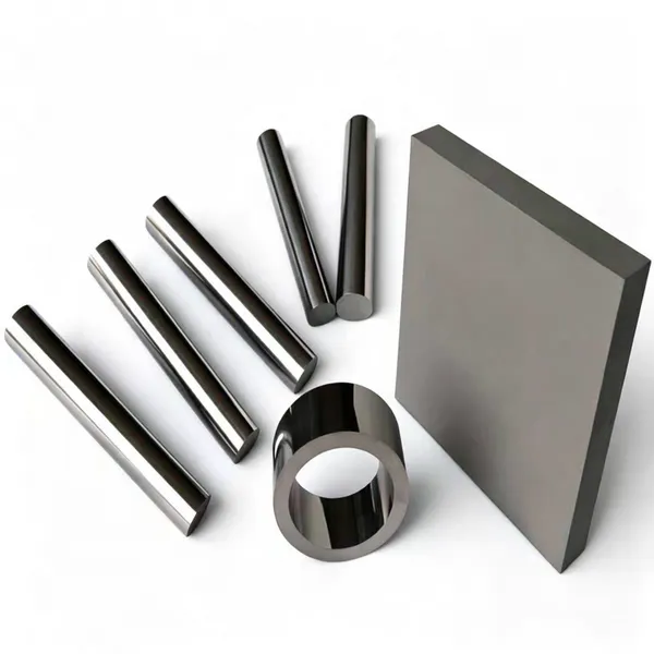
Polished Tungsten Carbide Hollow Rods for Precision Machining ApplicationsNegotiableMOQ: 1 Piece
-
Tungsten Carbide Saw Tips for TCT Circular Saw Blades and Woodworking CuttingNegotiableMOQ: 100 Pieces
-
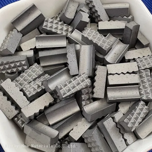
Tungsten Carbide Gripper Inserts for Oilfield Slip Assemblies – YG8/YG6/K10 Grades, High Hardness & Wear ResistanceNegotiableMOQ: 5 Kilograms

-
Precision Carbide Sleeves OD 5-50 mm ID 2-30 mm Concentricity Max 0.005 mm Ra 0.2 um CNC GroundNegotiableMOQ: 1 Unit
-
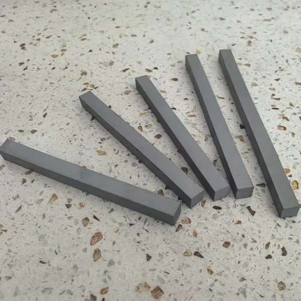
Submicron Tungsten Carbide Strips 2x8x330mm Ground Tolerance ±0.02mm HRA 92.0NegotiableMOQ: 10 Pieces
-
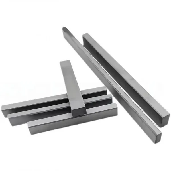
VSI Crusher Carbide Strips and Bars for Machine Tool Plane Blades Wood Cutting ToolsNegotiableMOQ: 10 Units
-
Yg8 Standard Tungsten Carbide Tips Ss10 for Stone Cutting ToolsNegotiableMOQ: 5 Kilograms
-
Tungsten Carbide Circular Saw Blade for Slitting Slotting Flat Tooth Saw Blades Cutting Metal Stainless Steel Aluminium Custom OEM Factory Bulk PriceNegotiableMOQ: 1 Blade
-
Tungsten Carbide Woodworking Blades – Replacement Cutting Blades for Wood Carving, Trimming & Planing ToolsNegotiableMOQ: 1 Box
-
Custom Carbide Wear Components From Samples and Prototypes to Volume Production WC-Co SupplierNegotiableMOQ: 10 Blades
-
Custom Tungsten Carbide Wear Parts Non-Standard Shapes Produced to Customer Drawings WC-CoNegotiableMOQ: 10 Blades
-
Tungsten Carbide Strips and Plates PYG7 Submicron Grade M10 Ultra High Strength Custom SizesNegotiableMOQ: 10 Blades
-
Tungsten Carbide Strips and Plates PK08 Grade K30 High Strength Impact Resistant Custom SizesNegotiableMOQ: 10 Blades